The working environment
An inspector photographs the curtain wall from permitted observation points. The demonstration focuses on the panel area labelled C3.
BUILT ENVIRONMENT
Locate visible changes on buildings and infrastructure, then turn an observation into a focused inspection task.
VISION IN CONTEXT / 02
Move from the whole facade to a specific panel, compare a synthetic inspection view, and prepare a maintenance follow-up.
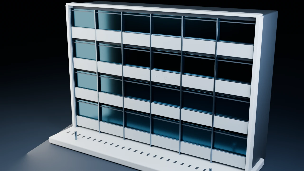
A finding gains context when the elevation, access route and inspection zone stay connected.
The camera movement explains the scene. The fixed evidence view below is a separate synthetic capture, with no live inference.
FROM OBSERVATION TO A DECISION
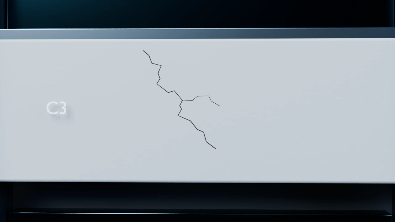 Panel C3 · joint area
Compare two authored states. This is not a record of elapsed time or a verified repair.
THE NEXT STEP NEEDS CONTEXT
Focus on crack-like marks at curtain-wall joints, water staining below facade details and blocked drainage grilles. The application direction uses visual localisation and same-location comparison to help inspection and maintenance teams find the relevant element and prepare the next visit.
An inspector photographs the curtain wall from permitted observation points. The demonstration focuses on the panel area labelled C3.
The facade inspector checks the marked joint. The maintenance coordinator needs its exact bay and the image needed for the next visit.
A close-up of a crack-like line may omit the wider facade. The next team then has to work out which joint to revisit.
The concept locates the joint within the facade view and highlights the visible line. It links the close-up to bay C3, keeping the finding separate from any conclusion about its cause.
Prepare a follow-up item naming the joint, location and inspection question. The next visit can capture the same area and append a matched view.
Give the next inspector a location to visit and a feature to look for. The maintenance coordinator can prepare a specific task instead of forwarding an unexplained photograph.
ILLUSTRATIVE WORKFLOWS — the following records are fictional examples, not customer cases or live analysis.
A dark line beside a joint may be difficult to distinguish from the joint edge, a shadow or a surface crack. A close-up also needs enough facade context to locate the finding.
Pair the facade overview with a close-up of bay C3. Keep the bay label and surrounding joints in view so the location can be matched on a later visit.
The proposed task locates the joint and highlights the adjacent line-shaped feature. The inspector compares the crop with the overview and selects the area requiring a closer site check.
Prepare a follow-up for the specific facade bay, with the joint crop and the question to resolve. Cause, dimensions and repair decisions come from the appropriate site assessment.
Help the inspector point a colleague to the same joint and distinguish the marked feature from the surrounding facade.
Leaves and loose material can cover a roof drainage grille. A maintenance team needs to know which outlet is affected and what to check after clearing it.
Capture the labelled outlet and a top view of its grille during the normal inspection route. Include enough roof context to identify the access location.
A proposed vision task locates the grille and marks areas covered by visible debris. The inspector checks the original view and confirms the asset label before creating a maintenance item.
Prepare a task for outlet D2: inspect the marked grille, clear debris under the existing maintenance procedure and take an after-work photograph.
Give the maintenance team a named outlet, a visible problem area and a clear image to capture when the task is complete.
A stain below a window sill can look different after a lighting change. Property staff need to compare the same wall area before describing an apparent change.
Use the window corners and sill as visual anchors. Pair the current image with the earlier visit and record the capture conditions for that north-elevation bay.
The concept aligns the two views around those anchors and outlines the visible stain in each. The inspector compares its extent while checking for shadows and different wet or dry conditions.
Attach the paired views to the facade maintenance item. Specify the next location and capture view, or request a site check of the associated sill and joint.
Help property staff discuss what visibly changed at one location and give the next inspector a repeatable photograph to take.
The scope is agreed for the specific task. These are deliverables to define together, not a claim that a configured system is already available.
Named facade bays, joint intersections and drainage outlets linked to the image views the team uses.
Overview and close-up pairs, repeat-view anchors and capture conditions for useful comparisons.
A marked joint, stain or grille alongside its location, inspection question and proposed maintenance follow-up.
Compare flags with inspector labels and test whether another team can locate the element and repeat the required view.
An editable planning template, created on this device. Nothing is submitted.
It illustrates locating a joint and marking a visible crack-like feature with its facade position. It does not infer the cause or structural significance of the line; those are questions for the relevant inspection.
No specific platform is assumed. The task needs a clear permitted view and enough location context; it may start with existing site photographs before capture options are evaluated.
Keep the same window or joint anchors in both visits, align the views and show the stain outlines together. Capture conditions remain visible so the inspector can judge whether a difference deserves follow-up.
The exact asset or bay, a marked photograph, the specific check or maintenance action, and the image required on completion. These fields can be scoped around the team’s existing work-order format.
START WITH A SPECIFIC TASK
Discuss the environment, equipment and evidence your project needs.